Installing Indian Cam Lobes.
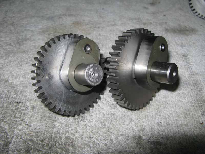
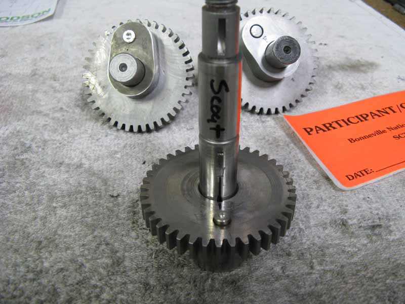
A Finished Set of Indian Scout Cam Gears with "Press-On Lobes.
Please note: Chief cam/gears are wider than Scouts, and their shafts are also longer. These shafts are not interchangable, and using the wrong shaft will cause problems! Chief front cam shafts for the aluminum oil pumps can be shortened for use in "648" type Scouts. Chief shafts for the iron oil pumps can be shortened for iron pump Scouts.
Make sure the cam shafts do not extend any more than 5/8" (.625") past the cam lobe edge. Otherwise, the shaft can extend into the flywheel case, and the right crank-pin nut will hit the shaft, and then bad things happen! I've seen it, and it's real bad.
Original Indian cam lobes were part of the cam/gear assembly. Since the original cams offer little to no performance, tuners have been making various performance cam grinds using new "Press-On" lobes. This requires the original lobe to be ground back with a precise flat surface, and ground back to accept the new lobe.The cam/gear needs to ground back precisely so that after adding my new cam lobe (.438" wide), the finished width is the same as the original cam/gear assembly. You can add or subtract a few thousandths to modify the cam width to correct for any incorrect cam end-plays. The original cam/gears need to be measured for end-plays in the cam chest, cleaned, and tested with a new cam cover gasket. With a set of calipers, carefully check the front and rear cam end-plays. The spec is .004"-.010" for the front cam, and it's .004"-.006" for the rear cam. It is important to get as close as possible here. If there is no end-play, the cams will spin out the case bushings! If too loose, the ignition timing will wander around, and idle poorly. It's important!
Chiefs cam/gears are 1.125" wide from the outer surface of the gear to the inner surface of the lobe (Scouts are .875" wide). Actually it is best to custom fit the lobes to a precise fit to the specific motor that the cam lobes will be used in. It is likely that at some point the cam shaft bushings have been replaced. The inside width within the cam chest for the cam/gear is not necessarily the same as when it left the factory. If the cam/gear is in a bind between the bushings, the bushings will spin in the case, and create real trouble! If they are loose in the cam chest, there is no issue with the front cam, but the rear cam (which drives the distributor), can cause the ignition timing to be erratic. I like to see .006" cam shaft end play once the cam cover is fully tightened. I have repeated this, because you can't ignore this!
The end play can be influenced by the cam cover gasket thickness. In all of my years working on Indians, I have seen many different gaskets with different thicknesses. This can be dangerous! Once the cam cover is on, there are (4) bushing combos that need the right clearance, or you will have problems. The first two are the lifter pin bushings, and the lifter pairs are exactly 1.000" wide, or .500" wide per lifter. If these have no working clearance, they will spin out the pin case bushings, and wreck your cases. The other is the two cam shafts end-plays. So, I like to setup a cam chest with the thinnest possible gasket that I can find. There are several types available in varying thicknesses. If you are setup for a thin gasket, you can't get in trouble if you go to a thicker gasket later. If you do, you will increase clearances, and only the rear cam with more end-play is a slight problem. But, if you setup the cam chest with a thick gasket, and go to a thinner gasket later, you will lose all your clearance, and start to spin out bushings. Wrecked cases!
To check the end-plays, use a good set of calipers, and after cleaning, and assembling the cam chest with the thin gasket that you are using, tighten all the screws, and take a reading with the cam shafts pushed inwards, and then take another reading when pulling the shafts outwards. Check it several times, and average the results. This needs to be very correct! If there is an excess of play (.012" as example), then the finished new cam/gear should be made up .006" wider than the width of the original cam/gear before grinding, and assembling. If there is less than .006" end-play, then you should reduce the width of the finished cam/gear assembly accordingly.
Tools
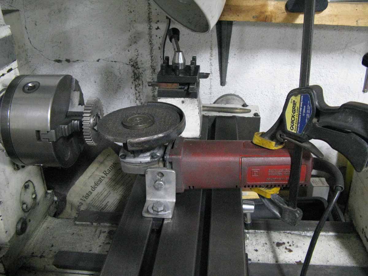
You will need to make some simple tools using some tubing, and a short shaft. Look at the pictures. They need to be made to give good solid "square" surfaces, or you can wreck the cam lobes, or shafts. Here is a pic of all the tools that I use for this install. I use a common angle grunder with (2) angled feet to clamp to my lathe bed with "T-nuts". I have a pistol grip clamp to run the angle grinder (I take .005" cuts at a time).

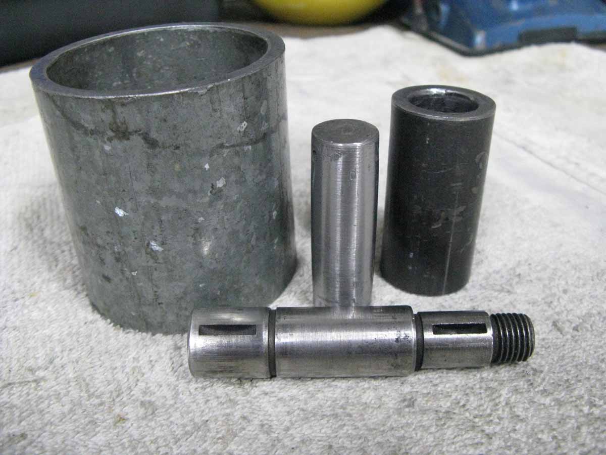
These are the "pressing" tools that you need to make. Mine have the following dimensions. They are just right in size! The large diameter tube is a piece of common 2" Galvanized pipe with an ID of: 2.098", and OD of 2.382". The length is 2 1/2" long, and cut very square. It's OK if it's not exact, but this the best size. Go find some! The smaller tube has a good width to contact the new cam lobe surface. The broader, the better. It will support the cam better while pressing, without doing damage.My tube is 1" OD, and .645 ID, by 2" long. I opened up a piece of 5/8" ID on the lathe. It took just a tiny bit off. The short shaft is a 2" long piece of 5/8" bar stock, or a bolt shank. But, it's OD needs to be cut down to about .618", so it can slide inside the .622" cam/gears when pressing. Bevel it at both ends. Be very careful with the alignment before pressing. The cam shaft shown has been cut down in length, and is used to support a cam/gear that has just been rough cut off, beveled, and pressed onto this shaft for lathe/ginding. You want to remove the shaft where it is in the bushing, and the cam lobe, plus some slack, so when grinding, you won't hit the shaft. I like to use an old worn out "Rear" shaft, because it has a longer bushing surface for a better "grab" in the lathe. Bevel everything before doing any pressing!
Pressing Shafts
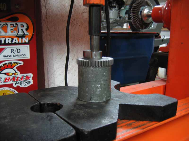
Press out both shafts using a press. Always press the shafts out from the "case end" of the shaft! The screw end of the front shaft, and the threaded end of the rear shaft are delicate. When you find yourself pressing the rear cam lobe together, you will want to use a penny as a soft pad to protect the threaded end, when pressing from the other direction.
Cutting Off Cam Lobes
To remove the original worn out cam lobes, I found that the fastest, and easiest way was to use a "Cut-Off" air tool with a thin disc. I just hold it in the vice, and cut away. You want to mark it with a Sharpie" pen where to cut it off. Use the new lobe to show you where to mark it. I usually leave around .040" extra for grinding. I used to use an angle grinder, and it was torture! It took alot of energy. A Hack-saw is out of the question.
Grinding Cam Lobes to Width
I take the cut-off cam/gears, and I do a bevel grind on the hole edges for better pressing of the shortened shaft for lathe/grinding. I like everything very "Square" to the shaft center! I press the shortened shaft into the cam/gear for grinding, but I press it a bit short, so when I am at the end of my grinding, I still haven't hit the end of the shaft.
To grind the lobes back, I made up a simple surface grinder for my lathe using a "Milwaukee Angle Grinder", which has 2 threaded holes on each side of the wheel head for mounting grab handles. I made 2 angle brackets that mount to these holes, so I can then mount the angle-grinder to my lathe bed. I aim the grinding wheel to the center of the cam shaft. I leave at least .040" of material when I cut the lobe off, so I can finish grind the rest on my lathe bed. This is a delicate job, and must be done with care not to remove too much material. I mount the shaft in the lathe, and after finish grinding, the shaft will be just slightly inside of the ground surface. You grind off .005" at a time moving the lathe bed in, and out for each cut. With great care, you can reduce the width to the exact specification. The finished width of the ground gear needs to be the difference of the adjusted required finished width, minus the width of the new lobe. The ground surface can be touched on a belt sander to further smooth the surface slightly.
Pinning the Cam Lobes to the Gear
The lobes will be "Pinned" to the gears with a .249" piece of Stainless Steel rod for proper alignment. All Indian Cam/gears have a .250" hole which was there for indexing during the gear tooth cutting, and lobe grinding process. The new lobes are made in a manner, such that the proper cam timing will be found once a pin is installed through both the new lobe, and the gear. This pin is for location only, and not strength. The lobe, and gear both should have a .001" interference press fit to keep the lobes from moving. Special "offset" pins can be made to either advance, or retard the cam's timing. I make all of my cam lobes with a 3 degree advance when using a straight pin. This information can be found elsewhere in my "Cam Study" section. I make pins that are .100" wider than the finished cam/gear, and I counter-drill the ends, so that they will stake over nicely once they are hit with a punch, and heavy hammer. Sometimes, the cam/gear's pin hole has a little burr that is hard as diamonds, and a small grinding bit in a Dremmel tool used lightly will grind the needed clearance (or hone it). You want a slightly loose fit for the pin. Any extra slop should be avoided! The pin should be in place during all phases of the shaft installation.
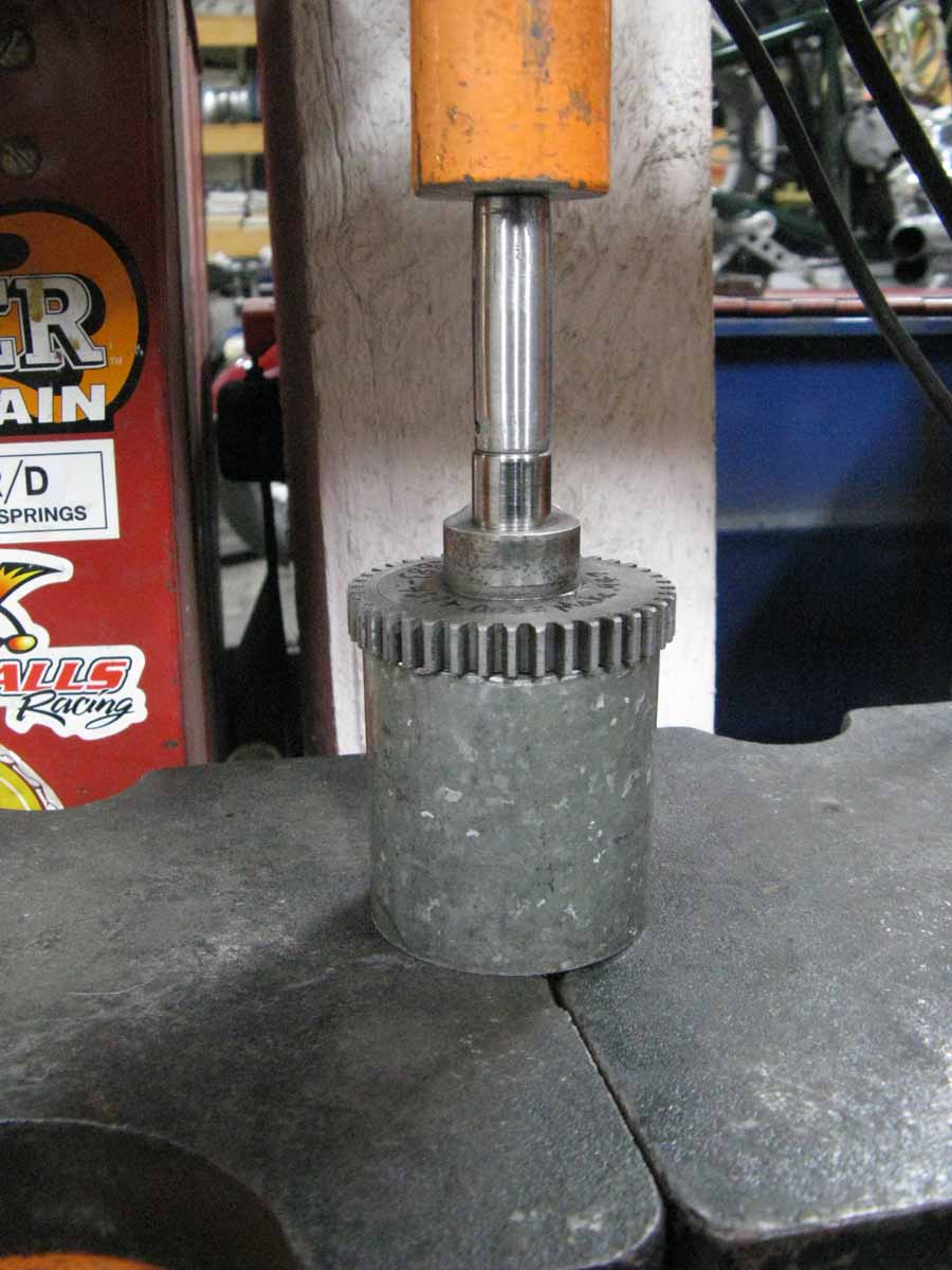
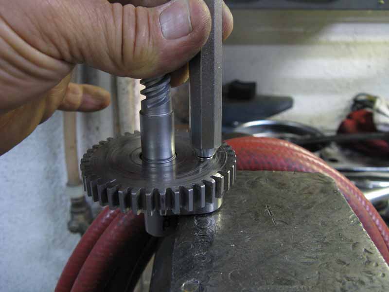
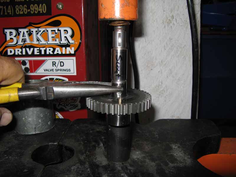
When installing the front cam/gear to the shaft, you first must orient the cam lobe, such that as it rotates, the lobe is running advanced. That means that if the pin hole is offset to one side of the cam's lobe, the wider half is running around ahead of the pin hole. This will advance the lobe function. This is very important , so that proper cam timing is found. When looking at the lobe side of the front gear, the gear turns clock-wise, and the rear cam turns counter clock-wise. Just remember that the wider "meatier" portion of the cam's lobe is running ahead of the pin hole as it rotates. Look at the picture, and you will see a piece of large tubing used as a support for the gear, while the front shaft is pressed through the cam lobe, and then into the gear in one operation. Try to carefully line up the cam's hole and shaft while beginning the press. Press until the flywheel side of the shaft is 5/8" (.625") outside the cam lobe.
Staking the Pins
After the shafts are pressed in to the proper location, the pins need to be staked over. I use a punch with a custom ground end with a very shallow angle. I have .050" of the pin showing out both ends, and while supporting one end of the pin on a heavy vise, I hit the punch very hard. I flip it over, and stake the other side over. I then finish staking the pins with a medium sized hammer to dress them better. Sometimes there is an air gap that appears between the lobe, and the gear because of the shock of striking the pin. The lobe, and gear will need to be pressed slightly back together to close up the gap. I rest the gear on the large tube, and use the smaller tubing tool resting on the lobe, and gently press them back together. This may need to be done each time the pin is staked with the punch. I use a medium set of "Vice Grips" to clamp the cam/gear to the new cam lobe when staking the pin. Make sure the cam lobe, and the gear are tight up against each other when finished!
Scout Rear Cam
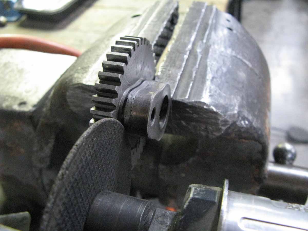
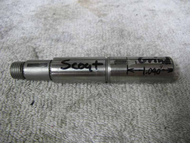
The rear cam is more difficult due to the fact that there is a key in the shaft to capture the gear in a precise spot. The rear cam shaft drives the distributer, and you don't want the shaft to slip off time! Care must be taken when lining up the key to the slot in the gear. In Scouts, the key must be shortened a bit, or the lobe will interfere with the key, and shear it off. It must be trimmed first as shown in the picture. I use a Dremmel "cut-off" disc to carefully grind away a portion of the top of the key, and not the shaft. The spec in the picture say 1.040", but make it 1.064" instead for a Scout.
I carefully draw a line along the shaft where the key is to help guide the shaft into the gear, and to make the key fall into the slot in the gear. It is a very close fit, and you must get the alignment perfect, or you will wreck the key!
I use the smaller tubing tool under the new lobe for support while pressing the rear shaft in. It is very important to get the shaft holes lined up perfectly in the cam lobe, and the gear at the beginning of the press. I also use a set of large needle nose pliers to hold the key firmly into the shaft, so it doesn't get pushed out during the press. I hold it during the entire press. Practice makes perfect, and make sure you have extra keys, because this press can be frustrating, and will sometimes need to be repeated. Press the shaft until you have 5/8" (.625") of shaft outside the cam lobe. At this point, you need to test the fit of the finished cam into the cam cover. The bevel gear that goes onto the shaft outside the cam cover should be able to slip all the way on (bottomed), and the shaft is free to turn. Check this!
Install the cams, and lifters and check the end-plays. The lifters should rise and fall easily!
CONTACT INFORMATION:
James R. Mosher
(505) 466-7870
(505) 466-6066 fax