Oil Pump & Scrapers
A "scraper" as used in the 1947 Chief was a good upgrade from the original sump casting used from 1932 through early 1947. The scraper is a flat 1/4" plate with a contoured blade behind it that sits very close to the outer edge of the rotating flywheels. It's job is to "scrape" off any excess oil from the flywheels when the motor is running. It doesn't actually scrape the flywheels, but rather sits about .015"-.020" off the edge (just enough to capture excess oil). The scraper blade is cocked at an angle, which helps to direct the oil now sitting in the bottom of the crankcase toward an oil fitting that the sump tube connects to. It is a simple system that works really well. The scraper is not restrictive, so an oil pump that has sat for a length of time has no trouble picking up oil to return to the oil tank. I use a 1947 Scraper on ALL bottom ends for Scouts, and Chiefs prior to 1947. In 1948, the Chief had this scraper cast into the cases, and there is only the threaded hole for the sump line fitting. To install a scraper to an older Chief, or Scout, there is a little trimming needed to the sump hole, and at the very bottom of the case joint, so the scraper can make it over to the left side wheel. Be very careful to not trim out too much metal, or the scraper gasket might leak!
The iron sumps used from 1932 through 1946 was pretty useless. It has just a short hose that dips down into the oil puddle in the bottom of the cases. That means that the flywheels were almost always exposed to this oil puddle, causing messy, and power robbing "oil windage" (when oil is being beaten about within the crankcase by rotating parts). Plus, the iron sumps had a little spring loaded check valve, which was probably supposed to hold oil instead of air in the sump hose. I have never seen an iron sump that actully would hold this oil, instead, when the oil drained through the check valve, only air was left in the sump tube. Now the oil pump had to prime itself by sucking air in the line that is against a closed check valve. This is a perfect scenario for "wet sumping". Wet sumping is when the oil pump can't get a grab of oil in the return gears, so no oil is returning to the oil tank, while the feed side of the pump is filling the crankcase full of oil. Wet sumping should always be avoided, because it makes a nasty mess of things. Oil will move past the rings so much that the top end gets soaked. Oil will come out the header connection at the cylinders, and it will definitely foul your spark plugs. The pistons will have burnt oil on them that will never go away. Avoid wet sumping! An Indian owner should ALWAYS open the oil tank cap, and observe returning oil once the bike has started everytime. When I see an iron sump, it goes into the dumpster every time!
The commonly seen "recirculating" iron pump came out in 1932, and went through several upgrades. Up through 1937 it was a smaller unit, and I can't personally comment on it, because I have never rebuilt one. I only see them on museum bikes, and never on the street. It probably moved small amounts of oil, but Burt Munroe used one on his famous Bonneville Streamliner Scout! In 1938 the larger common iron pump came out, but it is one year only, and can be identified by it's NPT type pipe thread fittings. It has the smaller plunger as well. In 1939 through early 1948 the iron pumps used machine fine thread fittings. The early pumps had a smaller feed plunger of about 1/2" diameter, while the later iron pumps had the larger diameter plunger at about 5/8". The larger plunger is always more desirable, because it will pump more oil! I assume that all pre-war plungers were the smaller type, but I'm not for sure. In 1947, the iron pump casting outer surface was flatter, as though it was machined down slightly. This is cosmetic only, and the internals are the same as other iron pumps. At some point in time, the top cap above the plunger had a short 1/4" piece of rod installed in the underside of the cap, and I am told that it was to break-up any air bubbles that might be sitting above the plunger. The iron pump with the large plunger is a very good pump.
There are usually only two things that happen to iron pumps. First, they can get rust inside the plunger hole, making it pump less oil, and be prone to wet sumping due to oil sneaking past the plunger (gravity!). This can be fixed by honing out the plunger bore, and building up the OD of the plunger with a hard-chrome surface. Starklite Cycle does this repair! The second problem has to do with the lower return gear plate. The return gears can push downward against the plate, causing wear grooves in the bottom plate, which makes the return gears lose alot of return pressure. Plus, oil will run down hill past these gears, and sometimes cause dry starts. By the way, when a pump won't begin to return oil when idleing, you can put a short piece of hose on the return line in the oil tank. Suck on the hose momentarily to get oil up into the return gears, and it will soon be returning oil to the tank. Be careful to not get a mouth full of oil! You can take the bottom return gear plate, and grind out the wear grooves on a smooth belt sander. The plate must be belt sanded perfectly flat, or the gasket WILL leak oil while running. Check the gears for bad wear. They will still work fine, even though they show some pitting. When assembling the plate, select the right gasket that gives just a touch of gear drag when the shaft is turned by a big screwdriver through the top hole where the distributor is mounted. I use a very thin smear of "HPF Hylomar" blue sealant. I also use Hylomar on all my gas, and oil connections! The Scout uses the small breather flapper disc behind the iron pump, but it is a poor excuse for a breather solution.
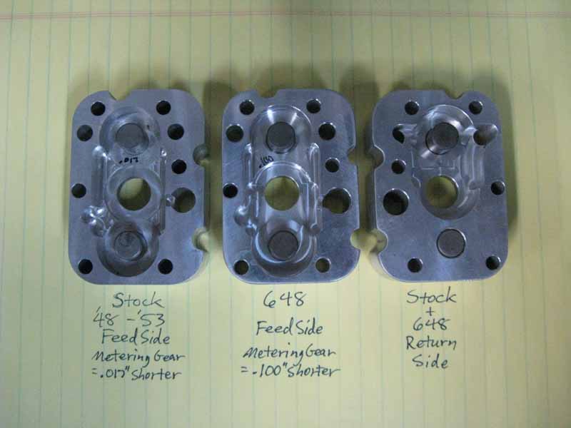
The aluminum pump is a very different pump. My opinion is that the iron pump is a better pump. The aluminum pump came out in 1948, and was used up to the end of production. In 1948, it was also used on the 648 "Big Base" Scout racers. The are two differences with the 648 pump. First, the oil lines mounted on the outer side surface, and ran rearwards to the oil tank under the seat. The second mod was done to the 3rd "metering" gear used in the set of feed gears. A stock pump's metering gear is .017" thinner than the other two feed gears, while the 648 pump's metering gear is .100" thinner than the other two gears. The 648 pump is supposed to flow alot more oil. I will soon see first hand, since I am adding the 648 pump bodies to my Twin-Scout. The aluminum pump is not a "plunger" pump, but rather a rotary geared pump that has a steady flow of oil (with un-impressive flow).
The aluminum pump's return side has just two gears much like the iron pump. Of course, it's purpose is to move more oil out of the motor than the pump can pump in. This makes sure that there is never too much oil in the crankcase. The feed side has three gears all in a row. The center gear is driven off of the front cam shaft, which has a slot in the end, unlike the cam shaft for the iron pump with it's spiral toothed end. The center gear turns one of the feed gears, and it is the same thickness as the driving gear (.375"). The metering gear is a little thinner than the other two, and it's job is to take a large portion of the oil picked up by the other two gears, and returns it to the supply side hole. Therefore, very little oil under very low pressure is entering the pinion shaft! Hopefuly the 648 pump will deliver more oil. I think this is a bad design. I would like to have seen a two gear pump with a spring loaded bypass to redirect oil. The aluminum pump's pump body is 100% aluminum, and gear wear in the pump body can be pretty bad. There were two springs with check balls used in the pump from the factory. One was inside the pump that slowed down the flow of incoming oil from the oil line. This ball, and spring should be removed. The other goes next to the pinion shaft opening to help prevent wet sumping. This ball and spring MUST be used, or the motor will fill with oil overnight! Drop the ball in it's recess, and then set the spring on top of it. The spring should protrude outside the housing edge by about 1/8" for proper spring tension.
Bob Stark has attempted to improve the performance of an aluminum pump by making a new gear set that uses 12 tooth "driven" gears (instead of 13), while the "driving" gears are still (13) teeth. The (12) tooth gears will spin faster, and 8 1/3% more rotation than the driving gears. There are larger voids between the teeth to carry more oil as well. They claim a 30% increase in flow, which is about the same as a plunger pump. He calls them the "Viagra" gear set!
On another subject, but still oil related, the lines in the oil tank can be placed in an optimum position. Never put the oil return line right next to the oil tank vent line, or oil splash will hit the vent tube, and end up on your garage floor. I bend the return line a little away from the oil cap, so the splash doesn't get all over the underside of the cap. If it hits the cap too much, there will be an oil mess around the outside of the cap. I also take a short piece of rubber vacuum hose, and put it on the end of the vent line. I then bend it forward, and away from the return line. You can play with the position of the rubber hose, so it never gets any oil splash into it.
I have seen on 58" stroker Scouts a problem where oil oozes up through the distributor body joint at the pump's sleeve. This is caused by improper breathing first, and possibly from excessive blowby from ruined rings. Oil mist is pumped into the cam chest, and there are ways for this oil to make it into the cavities in the back of the oil pump. That oil doesn't have a way to get back to the cam chest, so I drill a 1/4" hole in the cam cover to allow this captured oil to drain back. You will have to look for a good spot to drill this hole. Just imagine the lowest spot in the pump's rear void, and pick a safe spot on the cam cover to drill a hole.
Another good tip on attaching the cam cover, or oil pump. I like to use both Copper-Coat (or equivelant) on one side of the gaskets, and a not-setting sealant on the other side, so the cover, and pump can be removed, and re-installed without changing the gasket. I use "HPF Hylomar" blue sealant, which is fuel proof, and oil proof. I put Copper-Coat on the cam cover's gasket surface, as well as the gasket with a small modeling paint brush. I attach the gasket for the oil pump to the cam cover as well, instead of on the back of the pump. After a few minutes for it to setup, I place the gasket on. Then I install the cover to squeeze the gasket, and form a good fit. Then I remove the cover, and apply the "HPF Hylomar" to the case joint, and dry gasket surface both. On final assembly, there will be a little excess Hylomar oozing out, which can be cleaned up with a rag and lacquer thinner. Now, the cam cover or pump can be removed, and re-installed with the same gasket. Just use a little lacquer thinner to clean off any oil, and re-smear a little hylomar on the gasket surface. I have had great success with this setup. Actually the Hylomar can be re-smeared in the field while it is still oily! I also use Hylomar generously on intake manifold ring joints to prevent vacuum leaks. It's good for oil line fitting connections as well.
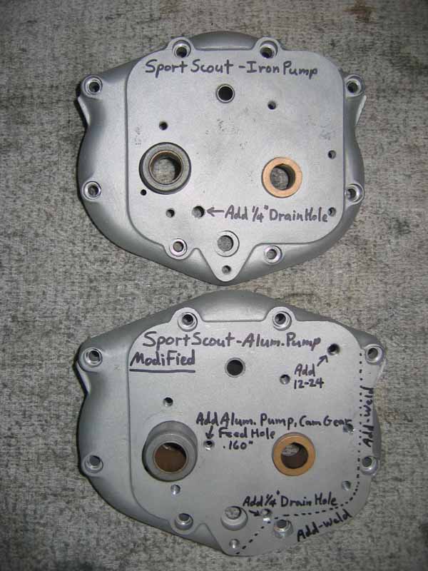
Here is a picture of a Scout cam cover modified for an aluminum pump, including the 1/4" drain hole. Welding, and machining is necessary.
Iron Pump Feed Plungers
Iron pumps first came out in 1938 for both Chiefs and Scouts. The 741s used the same pumps as a Scout with the larger 5/8" feed plunger, since they first came out in 1941. The smaller 1/2" feed plunger came out in 1938, and was also used in 1939. The larger feed plunger was used from 1940 through the 1947 Chief. The larger feed plunger is 56% larger in area than the smaller feed plunger, so you can expect up to 56% more oil delivery. I feel that in service, there will be somewhere less than the 56% increase, because of the back pressure of the crank pin restricting some oil from the higher volume larger feed plunger. The smaller pump will deliver adequate oil delivery in a Scout or Chief that is not ridded too agressively. An Indian actually needs very little oil to lubricate itself, but the other job for the oil is to cool the pistons. There would be slightly less cooling, so if you are a hot rodder, you might want to find a pump with the larger feed plunger. Otherwise, this feed plunger size is the only difference between the (2) pumps. These iron pump feed plungers rotate in use, and there is a short special screw plug that has a hardened tip that runs inside, and against the rising groove in the middle of the feed plunger. It's like a roller coaster, and makes the plunger rise and fall once for each rotation of the plunger. The front cam shaft has a spiral gear on the outside end of the shaft, which drives the feed plunger to rotate. So as it rises, and falls, there is an open "window" port that lets oil fill in, then get pushed out as the feed plunger rotates.
On top of the iron pumps is a large screw in cap above the feed plunger. At some point, Indian added a 1/4" shaft extending about 1/2" down from the bottom side of this cap. They drilled a 1/4" hole in the underside, and pressed in the 1/4" shaft. It's purpose was to break up any air bubbles above the feed plunger. These pumps have very little suction, and rely mostly on gravity feed for oil to enter the plunger. For that reason, it is very important to have a zero restrictive downward flow of the feed oil. Oil lines can not approach an iron pump from below! You can not have an oil filter in the feed line. Oil filters must go on the return side. Jerry Greer's sells a nice oil filter kit for Chiefs, but can also be remotely mounted on a Scout. If you use this filter, get the fre flowing "cheaper" filters from Napa. Ask for the cheap one. Otherwise, sometimes it is hard to get the oil returning on a cold start. You can also use the tubular shaped filter that drops into the tank over the return line, but oil changes require a thorough cleaning of the oil tank.
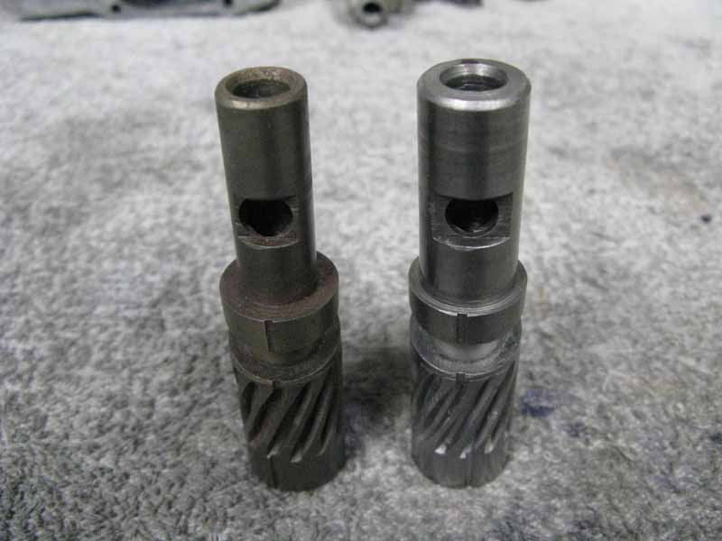
Here is a picture showing a 1938-1939 small 1/2" feed plunger, on the left, and a 1940-1947 larger 5/8" feed plunger on the right.
CONTACT INFORMATION:
James R. Mosher
(505) 466-7870