Transitional//EN">
Scout Racing Cams
Scout Racing Cam Profiles
$150.00 per set of cam lobes, including pins.
I found it necessary to come up with my own new performance cam
profiles, because they are just NOT available anywhere (until now!). After
determining the physical characteristics of the cam chest, I concluded that
.423" lift is the practical limit for a Scout motor. I have designed (8)
seperate cam lobe profiles (for Street/Strip, Road Racing, Flat Track, and Land Speed
Racing). After alot of real time testing, I settled into just (3) profiles, which have been very successful. At first, I went to Andrews Cams for some prototypes, and later settled in with a local Los Alamos machine shop that is very high tech. They CNC my cam lobes from "A-2" tool steel blanks. Then I hand dress them, and heat-treat them to Rockwell 60-62.The factory original cam/gear combo was made from "8620" gear steel. It's fine for gear teeth, but not for cam lobes. Most of the original cam lobes show severe wear from the rollers. The gear steel has a very thin "case hardening" of around .030" thickness, which just can't support the valve spring pressures. My cam lobes are super-tough, and will last forever. You can even swap them (front to rear), and turn them around for a new roller to cam lobe surface at a later date.
I get asked for cam lobe/gear combos like original, but it is not cost effective based on the volume that I would need to make (especially since I am selling 5 different profiles for Chief and Scout). Plus, the Indian cam chest has several oppertunities for cam degree error. They are: pinion shaft key locations (2 keys), pinion gear error (1 key), front cam gear teeth error, and rear cam gear error. Therefore, I prefer the "Press-On" cam lobe, which CAN be dialed in for a perfect cam timing. This is done by making special "Offset" pins per cam to get the timing you desire. This timing is the amount of cam advance or retard compared to the profile design. I believe that all Indian performance cams can benefit from 3 degrees of cam advance (in crank degrees). All my cam lobes have the 3 degrees advance built-in. That's done by shifting the 1/4" pin hole an exact amount. It is important to not get the cam lobe backwards! In most cases your cam will degree out to within 1/2 degree of the desired 3 degrees of advance. This is with using the 1/4" "straight" pins that I include. There is another page on my web-site that addresses the "Offset" pins, and the degreeing process. It's really for the serious racers. The factory cams all ran retarded, which just loses power.
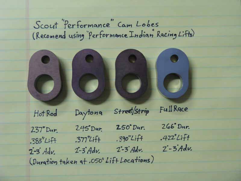
The picture shows a "Full Race" cam, but I never made it. It's just too radical. But the other (3) are available. The "Hot Rod" cam has the least duration to preserve some good low-mid power, and alot of lift. Flat-Heads like alot of lift, and the factory never offered anything above .330". Scout power was really held back! This is a good "Hot Street" cam, which would also work well in Vintage Road Racing. It's good in a 45", and great in a 58" Scout. My "Daytona" cam has more duration, and a high lift. It gives up a small amount of low-mid power, but makes more at higher RPM. It's a good choice for Road Racing or LSR racing. My "Street & Strip" cam has the most duration, and lift. It is best suited where high RPM power is needed. It's a good choice for Vintage Flat Track, with low gearing. It is also a good cam for "Hooligans" that like that nice "cammy" sound. My Twin-Scout uses the same 250 degrees duration, but with .423" lift. It pulls real strong at very high speeds (best speed was 177 mph).
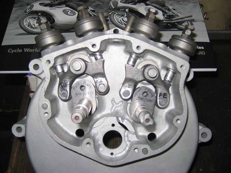
Here you can see my racing lifters in the cam case with (2) of my early
dished flank cam prototypes.
See my "Tech Talk" section for instructions on installing cam lobes.
CONTACT INFORMATION:
James R. Mosher
(505) 466-7870